Deconstructing a Heat Exchanger Its Main Parts
The Heat Transfer Surface: Core of the Exchange
The heat transfer surface is the physical barrier where thermal energy moves from one fluid to another. This component's design and material are paramount to the exchanger's efficiency and longevity. The two most common forms are tubes and plates.
Tubes
Tubes are the foundational heat transfer element in shell-and-tube heat exchangers. Manufacturers produce them using two primary methods. Seamless tubes originate from a solid metal billet, which is heated and extruded into a continuous, joint-free pipe. Welded tubes are formed by rolling a flat metal strip and welding the seam. While effective, tubes are susceptible to harsh operating conditions. Failures often arise from environmental factors inside the exchanger.
Common tube defects include:
·Corrosion and Erosion: Chemical reactions and fluid friction wear down both internal and external tube surfaces.
·Cracking: Fatigue from temperature and pressure cycles can cause cracks, especially near the tubesheet.
·Fretting: Tube vibration can cause them to rub against baffles or other tubes, leading to wear.
·Pitting: Localized corrosion, often driven by bacteria or poor water treatment, creates small holes or pits.
Plates
Plate heat exchangers use a series of thin, corrugated plates instead of tubes. These plates create complex channels for fluid flow, maximizing the surface area for heat transfer within a compact space. The pattern and angle of the corrugations are critical design features. A higher corrugation angle, for example, increases turbulence. This turbulence enhances the heat transfer rate but also results in a higher pressure drop across the unit. Engineers must balance thermal performance with acceptable pressure loss.
Material Selection
Engineers select materials based on the application's temperature, pressure, and fluid chemistry. Carbon steel is a common, cost-effective choice for many standard applications. However, its susceptibility to corrosion can lead to higher maintenance costs over time.
For demanding or corrosive environments, designers often specify exotic alloys like stainless steel, titanium, or nickel alloys. These high-performance materials offer superior durability and corrosion resistance, justifying their higher initial cost by ensuring long-term operational reliability.
The challenge always lies in balancing the required performance with the project budget. Proper material selection is a critical step that directly impacts the heat exchanger's lifespan and safety.
The Shell and Housing: The Outer Boundary
The shell is the heat exchanger's outer casing, serving as both a container and a structural backbone. It directs the flow of one of the working fluids and provides the necessary strength to handle internal pressures and external loads.
Containing the Process
The shell's most fundamental job is to contain the shell-side fluid, guiding it across the tube bundle. The design of the shell directly influences fluid dynamics and thermal performance. The Tubular Exchanger Manufacturers Association (TEMA) classifies shells based on their flow path, allowing engineers to select a design tailored to a specific application. ⚙️
| TEMA Shell Type | Primary Function / Application |
|---|---|
| E | Most common, suitable for general industrial process cooling. |
| F | Provides a longitudinal flow plate for true counter-current flow. |
| G & H | Ideal for phase change applications like reboilers and condensers. |
| J | Used for low shell-side pressure drops, often in vacuum service. |
| K | Specifically for kettle reboilers, allowing vapor to disengage from liquid. |
| X | A crossflow shell for very low pressure drop applications, like condensing vapor. |
Each type offers a unique advantage, from maximizing thermal efficiency to minimizing pressure loss.
Providing Structural Integrity
As a pressure vessel, the shell must safely withstand the system's operating pressures and temperatures. Its structural integrity is paramount for operational safety. The American Society of Mechanical Engineers (ASME) Boiler and Pressure Vessel Code (BPVC), particularly Section VIII, provides the essential rules for design, fabrication, and inspection.
Recent updates to the code have shifted design rules for shell-and-tube exchangers.
The 2023 edition of ASME BPVC Section VIII Division 1 now directs designers to use the rules in Division 2 for many heat exchanger components. However, most parts of the shell itself must still follow the applicable rules of Division 1.
Engineers determine a shell's final pressure and temperature ratings based on several critical factors:
·Adherence to design codes like ASME Section VIII.
·The material of construction and its performance at high temperatures.
·The calculated wall thickness, including a corrosion allowance.
·The quality of all welds and fabrication processes.
These elements work together to ensure the shell remains a robust and reliable boundary for the heat transfer process.
Channels and Nozzles: Directing the Flow
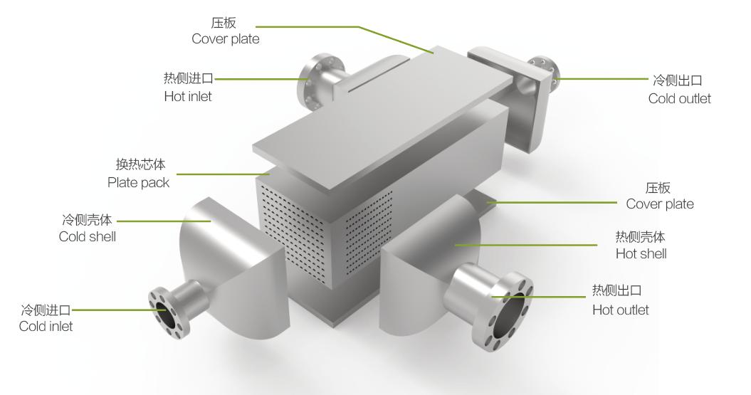
Channels and nozzles are the heat exchanger's traffic control system. They guide the working fluids into, through, and out of the unit. Proper design of these components is essential for managing flow rates, pressure, and overall thermal performance. They ensure fluids travel along their intended paths to maximize heat transfer.
Inlet and Outlet Nozzles
Inlet and outlet nozzles are the gateways to the heat exchanger. These flanged connections join the vessel to the plant's process piping. Engineers size nozzles to match the connecting pipes, ensuring a smooth transition. Because cutting a hole for a nozzle weakens the shell or channel, pressure vessel codes require reinforcement around the opening.
Designers often specify weld neck flanges for these connections. Their tapered hubs provide superior structural integrity and allow for thorough non-destructive examination.
·Standard Nozzles: A common design for moderate service includes a reinforcement plate paired with a weld neck flange.
·Self-Reinforced Nozzles: Modern options like Raised-Face Long-Weld-Neck (RFLWN) nozzles are forged as a single piece, which eliminates the need for a separate reinforcement pad and reduces fabrication costs.
The pressure drop between a nozzle's inlet and outlet creates a significant increase in fluid speed. This acceleration can cause fluid velocity to reach approximately 200 m/s. While this helps move fluid through the unit, such high speeds can also increase the rate of erosion, wearing down the nozzle material over time.
Internal Fluid Channels
Once inside the heat exchanger, fluids travel through carefully designed internal channels. In shell-and-tube units, the channel section (also called a header) uses pass partition plates to direct the tube-side fluid. These plates are essentially internal dividers that create a specific flow path.
Instead of letting the fluid flow through all the tubes at once, these partitions force it to travel back and forth in a multi-pass configuration. This design serves several key purposes:
·It divides the flow path within the channel cover.
·It forces the fluid to move through the tube bundle multiple times.
·It increases the fluid's travel distance and contact time with the heat transfer surface.
·It ultimately improves the heat exchanger's thermal efficiency.
By controlling the internal flow path, engineers can fine-tune the unit's performance to meet precise process requirements.
Essential Structural Heat Exchanger Parts
Beyond the primary surfaces and casings, certain structural heat exchanger parts provide critical support and boost thermal efficiency. Tubesheets and baffles are two of the most important of these components. They ensure mechanical integrity and optimize the fluid dynamics inside the vessel.
Tubesheets: The Critical Seal
The tubesheet is a thick metal plate that anchors the ends of the tubes. It acts as a stationary barrier, separating the tube-side and shell-side fluids. The connection between the tube and the tubesheet, known as the tube-to-tubesheet joint, is one of the most critical seals in the entire assembly. A failed joint leads to cross-contamination and costly downtime.
Manufacturers use several methods to create a durable, leak-tight joint:
·Seal Welds: These welds provide an extra layer of leak protection, which is especially useful with corrosive fluids.
·Strength Welds: These robust welds are designed to handle the physical load on the tubes. The process involves grooving the tubesheet hole to create a stronger connection.
·Roller Expansion: This mechanical process expands the tube against the tubesheet wall, creating a friction fit.
Research shows that combining welding with expansion creates the strongest joints. In one study, expanded-only joints failed at a load 28% lower than the tube's actual strength. This finding suggests that for many applications, relying on expansion alone is insufficient.
Leaks often occur due to issues like stress corrosion cracking, improper welding parameters, or under-expansion of the tube. Careful manufacturing is essential for these vital heat exchanger parts.
Baffles: Enhancing Performance
Baffles are plates installed along the length of the tube bundle. They serve two main purposes: supporting the tubes to prevent vibration and directing the shell-side fluid in a specific path. This controlled path forces the fluid to flow across the tubes, creating turbulence that significantly improves the heat transfer rate.
The most common type, the segmental baffle, creates a zigzag flow pattern. This design is effective but can create dead zones where fluid stagnates, leading to fouling and a large pressure drop. In contrast, modern helical baffles guide the fluid in a smooth spiral. This pattern nearly eliminates dead zones, reduces fouling, and lowers the pressure drop, which saves on pumping power.
Engineers carefully design baffle arrangements to balance performance and pressure loss.
| Baffle Design Factor | Effect on Pressure Drop | Effect on Heat Transfer |
|---|---|---|
| Increased Baffle Spacing | Reduces | Can reduce |
| Larger Baffle Cut | Reduces | Can compromise |
Proper baffle design is a key factor in optimizing the performance of these complex heat exchanger parts.
How the Components Work Together
The individual heat exchanger parts create a unified system for thermal management. The process begins when two fluids, one hot and one cold, enter the unit through separate nozzles. They travel along distinct paths designed to maximize their thermal interaction without allowing them to mix. This coordinated movement is the key to the exchanger's function.
Tracing the Tube-Side Fluid Path
The tube-side fluid enters the heat exchanger through an inlet nozzle on the channel section. Pass partition plates inside the channel direct this fluid into a specific set of tubes. In a multi-pass unit, the fluid travels the entire length of the tube bundle, makes a U-turn in the rear channel, and flows back through a different set of tubes. This back-and-forth journey increases the fluid's travel distance and its total contact time with the tube walls, improving thermal performance before it exits through the outlet nozzle.
Tracing the Shell-Side Fluid Path
Simultaneously, the shell-side fluid enters through a nozzle on the shell. Baffles inside the shell force this fluid to flow in a zigzag or spiral pattern across the outside of the tube bundle. This crossflow path creates turbulence, which enhances heat transfer. However, segmental baffles can also create stagnant flow zones, or 'dead spots,' next to the shell wall and in the shell's center. Engineers use computational fluid dynamics (CFD) to visualize and optimize flow.
·CFD simulations confirm how baffles create zigzag patterns and recirculation zones.
·This insight helps engineers refine baffle design to boost efficiency.
·Tools like ANSYS evaluate the thermal behavior of these complex flow paths.
The Result: Efficient Heat Transfer
As the two fluids flow through their designated channels, heat moves from the hotter fluid, through the tube or plate wall, and into the colder fluid. The effectiveness of this exchange is measured by the Log Mean Temperature Difference (LMTD), a key performance indicator. Engineers calculate it using a standard formula.
The LMTD is calculated as:
LMTD = (ΔT1 - ΔT2) / ln(ΔT1/ΔT2)
Optimizing the design of these heat exchanger parts can yield massive efficiency gains. For example, one project that redesigned a unit using additive manufacturing reduced its total mass by 81% and volume by 85%, demonstrating the power of innovative component design. Ultimately, one fluid leaves hotter and the other colder, achieving the desired process goal.
A heat exchanger's performance relies on its main components. These include the heat transfer surface, shell, nozzles, tubesheets, and baffles. Each of these heat exchanger parts plays a specific role in the system's function. Understanding them is the first step toward selecting the right unit for demanding services, such as those involving high pressures or corrosive fluids.
This knowledge is also essential for safe operation. Proper maintenance prevents leaks under high pressure and temperature, while monitoring key indicators like pressure drop ensures long-term reliability and efficiency. 💡
FAQ
What is the most important part of a heat exchanger?
The heat transfer surface, either tubes or plates, is the most vital component. This surface forms the barrier where heat moves from the hot fluid to the cold fluid. Its design and material directly dictate the heat exchanger's overall efficiency and performance.
Why do heat exchangers need baffles?
Baffles perform two essential jobs. They provide structural support for the tubes, preventing vibration and wear. They also guide the shell-side fluid across the tube bundle. This controlled flow path creates turbulence, which significantly boosts the heat transfer rate.
How do engineers prevent leaks in a heat exchanger?
Engineers focus on creating a strong tube-to-tubesheet joint to prevent leaks.
They use manufacturing techniques like roller expansion and strength welding. These methods create a durable, leak-tight seal that stops the tube-side and shell-side fluids from mixing, ensuring operational safety. 🛡️
What is the difference between a tube and a plate?
Tubes are cylindrical pipes that form the heat transfer surface in shell-and-tube exchangers. Plates are thin, corrugated sheets of metal stacked together. Plate designs provide a very large surface area in a compact volume, often leading to higher thermal efficiency.