How to Design a Plate Heat Exchanger
Plate heat exchangers (PHEs) are compact units consisting of thin, corrugated metal plates stacked together. These plates create alternating channels for hot and cold fluids to flow. The fluids stay separate (thanks to gaskets or welded seals) and typically flow in counter-current mode, maximizing the temperature difference along the length. As one fluid flows over one side of each plate and the other fluid flows on the opposite side, heat is conducted through the metal. This corrugated plate design induces turbulence and yields very high heat transfer coefficients, so plate heat exchangers often transfer heat more efficiently than shell and tube heat exchangers.
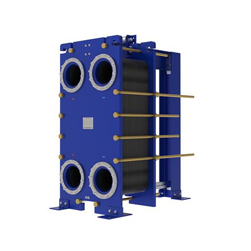
Gasketed plate heat exchangers use bolted plates and elastomeric gaskets (as shown above) to form sealed channels. Counterflow of hot and cold fluids through these plates maximizes thermal transfer.
Each plate has a large surface area and thin walls, which means rapid heat flow. In a gasketed plate heat exchanger, rubber gaskets between plates direct the fluids into alternating channels. (For welded designs, the plates are sealed by welding or brazing instead of gaskets.) In either case, the hot fluid transfers heat to the plate material, and the plate transfers it to the cold fluid on the other side. Because the cold and hot streams flow in opposite directions (counter-current), the temperature difference stays high across the unit, yielding very efficient heat transfer.
Key Steps in Designing a Plate Heat Exchanger
When designing a plate heat exchanger for a given application, engineers follow several key steps:
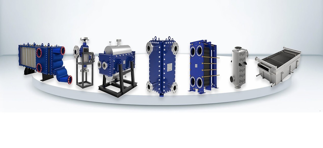
Choose the right exchanger type. First, identify the requirements: fluid type, temperatures, flow rates, pressure, space, and maintenance needs. For example, for mild conditions and easy maintenance, a gasketed plate exchanger is common. For very high pressures or aggressive media, welded types like the HT-Bloc or printed-circuit exchangers or TP designs (combining plate and shell features) may be needed. Specialized forms like wide-gap welded type are chosen for very viscous/solids-laden fluids or extreme conditions, respectively.
Calculate the heat duty and required area. Next, determine the thermal load Q (usually from process data or desired temperature change) and calculate the needed heat transfer area. Using the basic heat transfer equation Q = U × A × ΔT_lm , one computes the area A required. Here U is the overall heat transfer coefficient (estimated from fluid properties and plate characteristics), and ΔT_lm is the log-mean temperature difference between the fluids. Higher U or larger plate area yields a greater heat duty. In practice, the number of plates is chosen so that the total plate area meets A = Q / (U × ΔT_lm).
Estimate pressure drop. As fluids flow through the plates, there will be friction losses. Designers calculate the pressure drop on each side, using known flow rates, plate spacing, and corrugation patterns. The friction factor and channel length enter a fluid flow formula to ensure that the resulting pressure drop is acceptable for the system. If the drop is too large, one may add more plates (increasing area) or change plate geometry (e.g., larger passages in a wide-gap design) to reduce choking.
Select materials and components. Material choice depends on chemical compatibility and temperature. Common plate materials are stainless steel (e.g., 316L) for general use, titanium or nickel alloys for corrosive fluids, and special alloys for very high temperatures. Gaskets (if used) must suit the fluid (NBR, EPDM, Viton, etc.) and the temperature. In welded exchangers (HT-Bloc, TP, wide-gap), there are no gaskets, which allows very high pressure and temperature ratings.
Review the design and test if possible. After a preliminary design, good practice is to simulate or prototype the exchanger to verify heat transfer and hydraulics. As one guide notes, “verify the design using simulation or experimental testing to ensure… the desired heat transfer rate and pressure drop”. Adjust plate count, configuration, or operating parameters as needed to meet the targets.
These steps (selection, thermal sizing, pressure drop check, materials selection, verification) ensure a robust design. Along the way, referencing known product families can help: for instance, HT-Bloc welded plate exchangers use fully-welded plate packs for high-pressure service; Wide-gap welded exchangers offer enlarged channels to prevent fouling by slurries; and Printed-circuit exchangers use diffusion-bonded microchannels for extreme conditions.
Design Formula: Heat Duty and LMTD
A core formula in heat exchanger design is the heat balance:
Q = ṁ_h × c_{p,h} × (T_{h,in} – T_{h,out})
= ṁ_c × c_{p,c} × (T_{c,out} – T_{c,in})
or
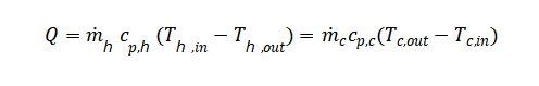
Where the subscripts h,c refer to hot and cold fluids. This ensures energy balance: the heat lost by the hot fluid equals the heat gained by the cold.
Another key relation is the heat transfer equation:
Q = U × A × ΔT_lm
Here U (overall heat transfer coefficient) represents the thermal conductance of the plate exchanger (it depends on fluid convection, plate material, and fouling), A is the total surface area of the plates, and ΔT_lm is the log-mean temperature difference between hot and cold streams. The LMTD formula accounts for the fact that the temperature difference changes along the exchanger. In simple terms, one first computes ΔT_lm = (ΔT₁ – ΔT₂) / ln(ΔT₁ / ΔT₂), where ΔT₁ and ΔT₂ are the temperature differences at the two ends.
With Q known and an estimate for U , the required area is A = Q / (U × ΔT_lm) . Designers often iterate: assume a plate pattern or material to estimate U(which can range from a few thousand up to 7000 W/m²·K for liquid-liquid PHEs), calculate A , then choose a plate count such that the sum of plate areas meets A . One may also use NTU-effectiveness methods for more complex sizing, but the U × A × ΔT_lm approach is a common starting point.
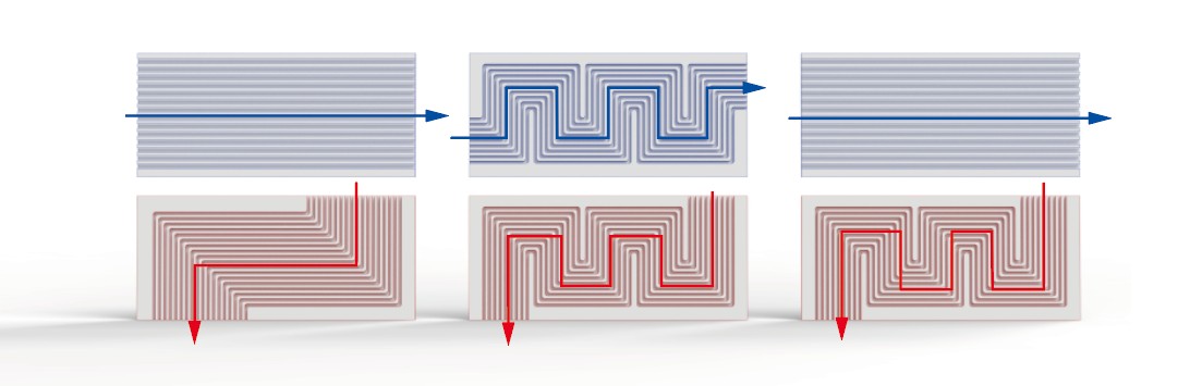
Printed-circuit heat exchangers rely on microchannel plates (shown above). Each plate is etched with narrow channels (blue and red flows) to create a huge surface area in a compact volume. The overall heat transfer follows Q = U × A × ΔT_lm , so their extremely large A/volume and high U give outstanding performance.
Industry Applications and Design Considerations
Plate exchangers are used across many industries. Each application has its own demands:
Chemical Processing:
Chemical plants often deal with corrosive or toxic fluids and may require high pressures or temperatures. Designs here favor welded PHEs (no gaskets to leak) made of special alloys. For example, an HT-Bloc fully-welded exchanger combines plate efficiency with shell andtube strength, enabling service in harsh chemical loops. Flow channels may need to be slightly larger than ultra-narrow to prevent fouling from suspended catalysts or solids. Materials like Hastelloy or titanium are common. The ease of cleaning is important – many processes allow for in-place cleaning (CIP) – so openable designs (bolted frames) can be used for maintenance.
HVAC (Heating/Ventilation/AC):
HVAC systems typically involve heating or cooling water and glycol loops at moderate pressures. Here, gasketed plate exchangers are very common due to their low cost and easy maintenance. They excel in energy recovery and chiller/condenser duties. The design emphasis is on maximizing efficiency in a limited space. Because fluids are relatively clean, narrow plates (high corrugation) can be used for maximum heat transfer. Gaskets allow simple disassembly for cleaning or adding plates if the capacity needs change. Typical materials are stainless steel (316L) and standard gasket elastomers. The pressure ratings in HVAC are modest (often < 20 bar), so standard gasketed units suffice.
Power Generation:
Power plants (fossil or nuclear) have high-temperature, high-pressure streams (steam, supercritical fluids). Printed-circuit heat exchangers (PCHEs) were first developed for nuclear and LNG and now find use in power cycles. PCHEs have microchannel plates diffusion-bonded into a solid block, giving outstanding strength and tiny, high-efficiency passages. They can operate up to ~1000 bar and 900°C, far beyond normal PHEs. In less extreme power applications (e.g., boiler feedwater heating), welded plate exchangers such as TP types combine compactness with robustness. These may have openable shells for maintenance and allow pressure drops that are acceptable for the cycle. In all cases, cleanliness is critical (no leaks), so fully-welded or diffusion-bonded designs are chosen.
Food and Beverage:
The food industry needs exchangers that are sanitary and easy to clean. Gasketed PHEs are widely used for pasteurization of milk, wort in brewing, and heating/cooling of juices. Plates are often stainless steel (sometimes 316L) with FDA-approved gaskets. Many units are built on open frames so plates can be flushed out or replaced for cleaning. For products with particulates (e.g., pulpy fruit juices, sugarcane juice), wide-gap plate exchangers are used. These have enlarged flow channels that tolerate solid pieces without clogging. Wide-gap designs are still welded and pressure-rated, but their channel shape prevents “dead zones” and blockages. The goal is gentle handling (to avoid product shear) while meeting tight temperature control. Often, CIP (clean-in-place) systems are integrated, and plate corrugation might be milder.
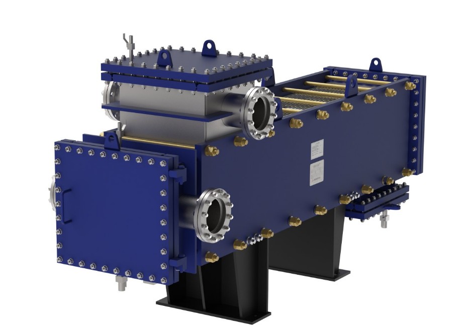
Wide-gap welded plate heat exchangers (like the blue unit above) handle viscous or particle-laden fluids. Large channels prevent clogging, while the corrugated plate design maintains high thermal efficiency.
Beyond these examples, nearly every industry from petrochemicals to pharmaceuticals uses plate exchangers in some form. Key requirements vary by sector: chemical plants stress corrosion resistance and pressure rating, HVAC focuses on compactness and serviceability, power plants on thermal performance and pressure, and food/beverage on hygiene and fouling resistance. By understanding the application’s demands, designers pick the right plate geometry, sealing method, material, and overall configuration.
Conclusion
Designing a plate heat exchanger requires a clear understanding of heat transfer principles and the specific process needs. Start with the basics: a plate exchanger works by counterflowing hot and cold fluids over alternating plates, achieving very efficient heat exchange. Then follow systematic steps: select the type (gasketed, welded, printed-circuit, etc.), calculate the thermal duty and required area, ensure pressure drops are acceptable, choose compatible materials, and verify the design.
Different industries will steer the choices: for example, HT-Bloc welded plate exchangers combine plate efficiency with high-pressure toughness, while Wide-Gap plate exchangers excel in food or mining applications with solids, and PCHEs deliver compact power-plant solutions. By blending these design principles with the appropriate product type and materials, engineers ensure that each plate heat exchanger performs reliably in its intended service.
If you need further consultation and discussion, please feel free to contact us.
Email: info@shphe.com
WhatsApp / Cell: +86 15201818405