Avoid Common Mistakes A Guide to Proper Heat Exchanger Sizing
Define Your Thermal Duty and Flow Rates
The foundation of any accurate heat exchanger sizing project is a clear definition of the system's thermal duty and fluid flow rates. Thermal duty, or heat load, represents the amount of heat that must be transferred between the two fluids to achieve the desired outcome. An incorrect heat load calculation is a primary source of sizing errors.
Specify Inlet and Outlet Temperatures
Engineers must first specify the inlet and outlet temperatures for both the hot and cold fluid circuits. These values define the temperature change (ΔT) required by the process. It is crucial to consider all operational scenarios. For example, ambient conditions directly influence system temperatures. Seasonal air temperature variations can alter the inlet temperature of a cooling fluid, affecting the system's overall performance.
Calculating Thermal Duty (Q)The heat load is calculated using a standard heat transfer equation. This formula connects temperature change directly to the system's thermal requirements.
Q = m x Cp x ΔT
·Q: Heat Load
·m: Mass Flow Rate
·Cp: Specific Heat of the Fluid
·ΔT: Temperature Change (Inlet Temp - Outlet Temp)
Determine Required Flow Rates
Accurate flow rates for both the hot and cold fluids are equally critical. Engineers obtain this data using precise measurement tools like ultrasonic, venturi, or magnetic flow meters. The specified flow rate directly impacts the heat exchanger's efficiency and operational costs.
Higher flow rates generally improve heat transfer efficiency and reduce fouling by creating a scouring effect on the plates. However, they also increase the pressure drop, which demands more pumping power. Conversely, lower flow rates reduce pumping costs but can lead to poor fluid distribution and an increased risk of fouling as particles settle on the heat transfer surfaces. Finding the optimal balance is key to an efficient and reliable system.
The Role of Pressure Drop in Plate Heat Exchanger Sizing
Pressure drop is the reduction in fluid pressure that occurs as it flows through the heat exchanger. This parameter is a critical factor in plate heat exchanger sizing because it directly influences both thermal performance and operational cost. An acceptable pressure drop must be defined to balance efficiency with energy consumption.
State Your Maximum Allowable Pressure Drop
Engineers must specify the maximum allowable pressure drop for both the hot and cold circuits. This value dictates the fluid velocity inside the unit. Higher fluid velocities create more turbulence, which improves the heat transfer coefficient but also increases pressure loss. The optimal design for plate heat exchanger sizing achieves the required heat transfer with the lowest possible pressure drop. The acceptable limit often depends on the application.
| Application Type | Typical Maximum Allowable Pressure Drop |
|---|---|
| HVAC (Commercial Systems) | 0.5 to 2 Pa/m |
| Industrial Facilities | Higher (due to robust systems) |
| Residential Buildings | Lower (for comfort and efficiency) |
Understand the Impact on Pumping Costs
A higher pressure drop requires more powerful pumps to circulate the fluids, leading to greater energy consumption. This directly increases long-term operational costs. Even a small oversight can have a significant financial impact. For instance, a 2 PSI increase in system pressure can raise annual energy consumption by approximately 1-2 percent.
Pro Tip: Investing in an optimized design with a lower pressure drop may have a higher initial cost but delivers substantial savings over the unit's lifetime.
Proper plate heat exchanger sizing that considers pressure drop yields impressive returns. Case studies show that optimized solutions can deliver:
·Up to 40% in energy cost savings.
·Payback periods as short as two years.
·Significant reductions in CO2 emissions.
This makes careful pressure drop specification essential for creating an efficient and cost-effective system.
Characterize Your Process Fluids
Beyond temperatures and flow rates, the physical properties of the process fluids themselves are fundamental to accurate heat exchanger sizing. Different fluids transfer heat and flow in unique ways, so providing detailed fluid data is essential for a correctly specified unit.
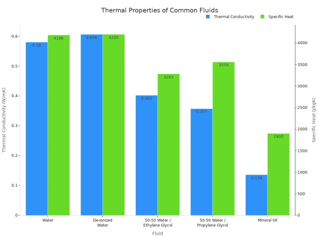
Detail Key Fluid Properties
Engineers must identify the specific heat, thermal conductivity, and density of both fluids. Specific heat measures a fluid's ability to store thermal energy, while thermal conductivity indicates how well it conducts heat. For example, water has a much higher specific heat and thermal conductivity than oils, making it a more efficient medium for heat transfer. Fluid density (ρ) is also a critical parameter, as it directly influences the pressure drop calculation and the required pumping power.
Account for Viscosity and Particulates
Viscosity, or a fluid's resistance to flow, is another crucial factor. Fluid viscosity typically decreases as temperature increases. Highly viscous fluids flow more slowly, which can reduce heat transfer efficiency and require special plate designs to maintain performance.
The presence of suspended solids or particulates in the fluid also dictates the heat exchanger's design. Clogging is a major risk if the channel geometry is too narrow for the fluid's contents.
Design Note: Standard plate-and-frame heat exchangers are suitable for fluids with very small particles (under 0.0625 inches). For fluids containing larger solids or fibers, a wide-gap plate design is necessary to prevent blockages and ensure reliable operation.
Plan for Fouling to Ensure Long-Term Performance
Over time, unwanted materials accumulate on a heat exchanger's surfaces in a process called fouling. This buildup degrades thermal performance and is a primary cause of inefficiency. Engineers must plan for this inevitability by incorporating a fouling factor into their sizing calculations.
What Is a Fouling Factor?
A fouling factor is a value that represents the thermal resistance added by a layer of fouling deposits. This deposition acts as an insulating barrier, which reduces the unit's overall heat transfer coefficient. The result is a steady decline in thermal performance, requiring more energy to achieve the same duty.
Common types of fouling include:
·Scaling: Mineral deposits like calcium carbonate precipitate from the fluid.
·Particulate Fouling: Suspended solids settle on the surfaces.
·Corrosion: Rust and other corrosion byproducts form an insulating layer.
·Biological Fouling: Algae, bacteria, and other microorganisms create a biofilm.
A fouling factor is not just a guess. It is a calculated resistance value derived from plant data that quantifies the impact of material accumulation on heat transfer surfaces.
Specify a Realistic Fouling Margin
Engineers use the fouling factor to add a calculated amount of extra surface area to the heat exchanger design. This "fouling margin" ensures the unit is oversized when clean, allowing it to meet performance requirements even as deposits build up. The goal is to achieve reasonable intervals between cleanings.
The appropriate margin depends heavily on the fluid's quality. The Tubular Exchanger Manufacturers Association (TEMA) provides standard values for different fluids. For example, untreated water requires a much higher fouling factor than distilled water.
| Fluid Type | Typical Fouling Factor (m².K/W) |
|---|---|
| Distilled Water | 0.00009 |
| River Water (Average) | 0.0002 - 0.0003 |
| Hard Water (>250 ppm) | 0.0005 - 0.0009 |
Specifying a realistic fouling margin is a critical balancing act. Too small a margin leads to frequent cleaning and downtime. Too large a margin results in an unnecessarily expensive, oversized unit.
Select the Right Materials and Plate Design

Selecting the correct materials and plate geometry is a final, critical step in the sizing process. These choices protect the unit from corrosion and optimize its thermal-hydraulic performance for the specific application.
Match Materials to Fluid Chemistry
Engineers must choose materials that are chemically compatible with the process fluids to prevent corrosion and ensure a long service life. For aggressive fluids like saltwater or certain acids, materials such as titanium or nickel alloys offer superior corrosion resistance. In food and beverage applications, stainless steel grades 304 and 316 are the industry standard due to their hygienic properties and durability.
Gasket material selection is equally important and depends on the operating temperatures.
| Gasket Material | Typical Temperature Range |
|---|---|
| Nitrile (NBR) | -40°F to 250°F (-40°C to 121°C) |
| EPDM | -60°F to 300°F (-51°C to 149°C) |
Note: EPDM gaskets are often specified for applications involving higher temperatures, while NBR is suitable for systems with oils and fats.
Choose the Correct Plate Configuration
The plate design directly controls the heat exchanger's efficiency and pressure drop. Plates feature chevron patterns that create turbulence, enhancing heat transfer. These patterns are defined by their "theta" angle.
| Plate Type | Heat Transfer | Pressure Drop |
|---|---|---|
| High-Theta | Higher | Higher |
| Low-Theta | Lower | Lower |
A high-theta design maximizes thermal performance but requires more pumping power. A low-theta design reduces pressure drop at the cost of some thermal efficiency. For fluids containing fibers or coarse particles, such as in the bioethanol or paper industries, a wide-gap plate design is necessary. Its wider channels prevent clogging and ensure reliable, uninterrupted operation.
Successful plate heat exchanger sizing requires a complete dataset. Engineers must define temperatures, flow rates, pressure limits, fluid properties, fouling factors, and materials.
Providing incorrect design parameters is a common mistake. An installed unit will not perform optimally if the designer receives inaccurate information.
This guide provides a framework for proper plate heat exchanger sizing, ensuring enhanced system efficiency and long-term cost savings.
FAQ
What happens if I oversize my heat exchanger?
An oversized unit wastes capital on unnecessary surface area. It can also cause control issues and thermal instability, leading to inefficient system operation and higher energy costs.
How often should a heat exchanger be cleaned?
Cleaning frequency depends on fluid quality and the specified fouling factor. Systems with poor water quality or high particulate levels require more frequent maintenance to maintain thermal performance.