The Ultimate 2025 Guide to Industrial Heat Exchanger Plates
How Do Heat Exchanger Plates Function?
A heat exchanger's effectiveness originates from the sophisticated interaction of its core components. Engineers stack a series of thin, pressed metal plates to form a plate pack. This assembly creates a network of parallel channels for fluids to flow through, facilitating efficient thermal exchange.
The Plate and Gasket Assembly
The plate and gasket assembly is the primary barrier preventing fluid cross-contamination. Gaskets line the edge of each heat exchanger plate, creating a secure seal for each fluid medium. This design also incorporates vented spaces between the gaskets, ensuring the purity of each fluid stream. For applications requiring maximum safety, such as in food processing or pharmaceuticals, double-wall plates provide an extra layer of protection. This configuration uses two plates between fluid channels. A leak in one plate allows the fluid to escape to the atmosphere instead of mixing with the other fluid.
Fluid Flow Dynamics
Heat exchangers achieve high efficiency through specific flow patterns. Typically, the hot and cold fluids travel in opposite directions in a counter-current flow arrangement. The hot fluid flows down one channel while the cold fluid flows up the adjacent channel. This dynamic maintains a significant temperature difference across the entire length of the plate. The consistent thermal gradient maximizes the rate of heat transfer between the two fluids.
The Role of Corrugations
The pressed patterns on the plates, known as corrugations, serve two critical functions. They provide structural rigidity and induce turbulence in the fluid flow. This turbulence disrupts the fluid's boundary layer, dramatically increasing heat transfer efficiency.
·Chevron Angle: The angle of the chevron (V-shaped) pattern is the most influential design parameter.
·H Plates: These plates have an obtuse (dull) chevron angle. They create high thermal transfer but also a higher pressure drop.
·L Plates: These plates use an acute (sharp) chevron angle. They produce a lower pressure drop at the cost of reduced thermal efficiency.
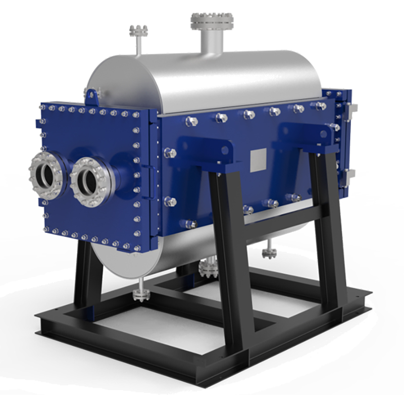
Key Types of Heat Exchanger Plate Assemblies
The assembly method of a heat exchanger dictates its operational capabilities, maintenance requirements, and suitability for specific industrial tasks. Engineers select from four primary assembly types, each offering a distinct balance of performance, durability, and flexibility.
Gasketed (PHE)
Gasketed Plate Heat Exchangers (PHEs) represent the most flexible design. In this assembly, a series of metal plates are compressed within a sturdy frame. Elastomeric gaskets fit into grooves along the edge of each plate, creating a tight seal and directing the two fluids into alternating channels. This construction allows for easy disassembly, cleaning, inspection, and capacity modification by adding or removing plates.
However, the gaskets themselves define the operational limits.
Note: Gasketed PHEs are designed for moderate conditions. They typically operate at pressures below 1.6 MPa (232 psi) and temperatures under 150°C (302°F). The specific gasket material, such as EPDM or Viton, determines the ultimate temperature resistance.
Their adaptability makes them a cornerstone in numerous sectors. Common applications include:
·HVAC: Used for space heating, cooling, and domestic hot water.
·Food and Beverage: Essential for pasteurization, product cooling, and general heating or cooling duties.
·Power Generation: Employed for lubricating oil cooling and heat recovery from exhaust gases.
·Industrial Processes: Applied in the chemical, pharmaceutical, and marine industries for a wide range of thermal tasks.
Brazed (BPHE)
Brazed Plate Heat Exchangers (BPHEs) offer a compact and highly efficient solution. This design eliminates the need for gaskets and frames. Instead, a stack of stainless steel plates is permanently bonded together in a vacuum furnace using a brazing material, typically copper or nickel. The result is a solid, hermetically sealed unit that is both lightweight and extremely durable.
The brazing process creates a single, pressure-resistant unit capable of handling significant temperature and pressure variations. The choice of brazing material directly impacts its durability in different environments.
| Brazing Alloy | Joint Strength | Corrosion and Oxidation Resistance |
|---|---|---|
| Nickel | Exceptional strength for high-stress, high-temperature applications. | Superior resistance to oxidation and chemical corrosion. |
| Copper | Excellent strength for moderate temperature service. | Effective but may require protection in corrosive settings. |
This robust, maintenance-free design makes BPHEs ideal for applications where reliability and a small footprint are critical. They are widely used as:
·Condensers, evaporators, or economizers in HVAC and refrigeration systems.
·Heaters and coolers in district energy networks.
·Components in hydronic heating and heat recovery systems.
·Cooling units for electric vehicles (EVs) and data centers.
Welded (WPHE)
Welded Plate Heat Exchangers (WPHEs) provide maximum durability for the most demanding industrial environments. In this configuration, corrugated plates are welded together to form a secure plate pack. This gasket-free design eliminates the risk of leakage from gasket deterioration, making it exceptionally reliable for handling aggressive fluids, high pressures, and extreme temperatures.
WPHEs combine the high thermal efficiency of a plate design with the robustness of a traditional shell-and-tube exchanger. This construction delivers several key advantages for high-pressure chemical processing and other heavy-duty industries like oil and gas or power generation. The welded structure ensures a longer operational lifespan by removing a common wear point. They can reliably operate at higher pressures than their gasketed counterparts, often reaching up to 30 bar compared to the 25 bar limit of many PHEs.
Semi-Welded
Semi-welded heat exchangers offer a clever hybrid solution, combining the strengths of both welded and gasketed designs. This assembly uses "cassettes," where two adjacent plates are laser-welded together. These welded cassettes are then stacked and sealed with traditional gaskets.
This unique structure creates two distinct channel types:
A welded channel: This side is fully sealed and contains the aggressive, corrosive, or high-pressure fluid.
A gasketed channel: This side contains the less demanding fluid and can be opened for cleaning and maintenance.
This design protects the gaskets from harsh media, extending the equipment's lifespan and reliability in challenging conditions. It allows a semi-welded heat exchanger plate to handle higher pressures and temperatures than a fully gasketed unit while retaining serviceability. This makes them a preferred choice for specialized applications, particularly in ammonia refrigeration systems where they function as condensers, evaporators, and oil coolers. They are also widely adopted in the chemical, petrochemical, and metal processing industries.
Understanding Plate Materials and Their Roles
The material of a heat exchanger plate directly governs its performance, lifespan, and suitability for a specific industrial process. Engineers select materials based on a careful balance of corrosion resistance, thermal conductivity, mechanical strength, and cost.
Stainless Steel (304/316)
Stainless steel is the most widely used material due to its excellent combination of strength, corrosion resistance, and value. The two most common grades offer distinct advantages.
304 Stainless Steel: This grade provides good corrosion resistance for general-purpose applications involving water, food products, and mild chemicals.
316 Stainless Steel: This grade contains added molybdenum. This element significantly enhances its defense against chlorides and acids, making it essential for marine applications, chemical processing, and environments with corrosive chloride gas.
While 316 is generally superior in acidic conditions, 304 can outperform it in highly oxidizing environments with very low halogen content.
Titanium
Engineers specify titanium for applications involving highly corrosive fluids, particularly seawater, brine, and chlorine. Its exceptional resistance to high-temperature ion corrosion prevents the severe damage that other metals suffer in marine environments. This makes it the material of choice for seawater desalination and coastal power plant cooling systems.
Although the initial investment for titanium is significantly higher than for stainless steel, its superior durability extends operational life. This longevity reduces long-term maintenance and replacement costs in aggressive settings.
Nickel Alloys (Hastelloy, Incoloy)
For the most extreme industrial environments, nickel alloys like Hastelloy and Incoloy provide unmatched chemical resistance. These materials are engineered to withstand aggressive media that would quickly destroy stainless steel or even titanium. They are essential for processes involving:
·Concentrated sulfuric and hydrochloric acids
·"Wet process" phosphoric acid
·Hot fluoride salts
·Chloride-induced stress cracking
Their robustness ensures operational reliability in the harshest chemical, petrochemical, and waste processing applications.
Specialized Plates for Challenging Industrial Fluids
Standard heat exchangers often struggle with complex industrial fluids. Processes involving slurries, pulps, or viscous liquids demand specialized plate designs to prevent blockages and ensure reliable operation. Engineers create customized solutions using erosion-resistant materials and optimized channel geometries to handle these demanding applications.
Handling Particle-Laden Fluids
Fluids containing suspended solids, crystals, or particulates require plates with unique flow channels. Wide-gap plates, also known as free-flow plates, are specifically developed for these conditions. Their design incorporates several key features to prevent fouling and blockages:
·Wide Channels: The space between plates can reach 6-16 mm, allowing solid-rich fluids to pass through smoothly.
·Reduced Contact Points: A special wave-like corrugation pattern minimizes contact between plates. This creates an unobstructed path that prevents particles from getting trapped.
·Smooth Flow: This design ensures fluid moves without stagnation or dead zones, which are common causes of blockages.
Managing Viscous and Fibrous Fluids
Industries like pulp and paper, food processing, and wastewater treatment frequently handle viscous or fibrous media. Free-flow plate designs are essential for these applications. The wider, unobstructed channels accommodate thick liquids and materials with high fiber content. This configuration allows uninterrupted fluid passage, which minimizes pressure drop and prevents the clogging that plagues standard plate designs. Even media with pulp fiber content up to 10% can flow efficiently through these specialized channels.
Design Principles for Reliability
Engineers follow strict principles to enhance the reliability and lifespan of specialized plates. Proper material selection is the first step. Choosing the right plate material, such as stainless steel or titanium, and gasket material, like EPDM or Viton, ensures compatibility with the fluid's chemical properties and temperature.
Note: Adherence to established industry standards is also critical. Compliance with guidelines from the American Society of Mechanical Engineers (ASME) and the Pressure Equipment Directive (PED) ensures the equipment's structural integrity and operational safety under demanding conditions.
How to Select the Right Plate for Your Application
Selecting the correct plate assembly is a critical engineering decision that directly impacts system efficiency, reliability, and total cost of ownership. This process requires a systematic evaluation of three core areas: the operational demands of the system, the chemical nature of the fluids, and the long-term challenges of maintenance and fouling.
Assessing Operating Conditions
The first step in selecting a plate is to define the thermal and hydraulic requirements of the application. Engineers must precisely quantify the operating temperatures, pressures, and flow rates to determine the necessary thermal performance and physical size of the unit.
The primary calculation is for the thermal duty, or heat load. This figure dictates the amount of surface area required for the heat transfer process. The process follows two main steps:
Calculating Heat Load (Q): Engineers first determine the total heat that needs to be transferred. This value is based on the process requirements, the fluid flow rates, and the desired change in temperature.
Calculating Required Surface Area (A): With the heat load established, engineers calculate the necessary heat transfer area. This is the total surface area of the plates where thermal exchange will occur. It determines the number and size of plates needed for the application.
To ensure the selected unit meets these targets, a thorough analysis of system parameters is essential. Key performance indicators include:
·Thermal Performance: Measure inlet and outlet temperatures for both fluid circuits to calculate the temperature differential (Delta-T).
·Flow Rates: Verify the flow rates for both the primary and secondary fluids using calibrated flow meters.
·Pressure Drop: Install pressure gauges at the inlet and outlet ports to measure the pressure differential across both fluid paths.
·Pro Tip: 💡 During operation, engineers monitor the pressure drop across the exchanger. A pressure drop greater than 5 PSI often indicates a potential issue, such as fouling or an internal blockage, that requires investigation.
Evaluating Fluid Compatibility
The chemical composition of the process fluids governs the selection of plate and gasket materials. An incorrect material choice can lead to rapid corrosion, gasket failure, and costly system downtime. Compatibility ensures the longevity and safety of the equipment.
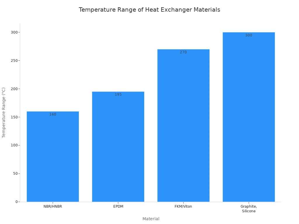
For gasketed units, the gasket material is often the most critical selection. Each elastomer has a specific range of chemical and temperature resistance.
| Material | Temperature Range | Best For | Limitations |
|---|---|---|---|
| NBR/HNBR | -20–140 °C | Oils, fuels | Low chemical resistance |
| EPDM | -30–165 °C | Steam, water, cleaning solutions | Not suitable for oils |
| FKM/Viton | -10–260 °C | Aggressive chemicals | Higher cost |
| Graphite, Silicone | up to 300 °C | High-heat, food-grade applications | Specialty pricing |
The operational temperature range is a decisive factor in material selection, as shown by the capabilities of different elastomers.
Specific industries have established best practices for material selection:
·HVAC & Refrigeration: EPDM is a standard choice for water-glycol systems. FKM is recommended for systems using HFO refrigerants or oils.
·Food & Beverage: Food-grade EPDM and high-grade silicones are common. FKM is used for processes involving aggressive cleaning chemicals.
·Chemical & Petrochemical: FKM (Viton) and other specialty elastomers are essential for handling harsh, corrosive substances safely.
Considering Maintenance and Fouling
Fouling—the accumulation of unwanted deposits on plate surfaces—is a primary concern in industrial heat exchange. It degrades thermal performance, increases pressure drop, and necessitates periodic cleaning. The design of the plate itself plays a significant role in mitigating fouling.
Research shows that the flow distribution within the plate channels is a crucial factor. Plates with different corrugation patterns can foul at significantly different rates, even under identical operating conditions. An improper design can create low-velocity or stagnant zones where particles and deposits easily accumulate.
For example, studies on steam condensation have shown that a heat exchanger plate with a 60° corrugation angle can significantly reduce the required surface area compared to one with a 30° angle, provided the pressure drop is not limited. However, the flow characteristics and fouling potential of each design differ. Therefore, engineers must select a corrugation pattern that promotes even flow distribution across the entire surface. This design choice helps maintain high fluid velocity, which creates a self-cleaning effect and minimizes the rate of deposit formation, ultimately extending operational cycles and reducing maintenance frequency.
A heat exchanger plate functions as the core engine of industrial thermal management, not merely as a passive component. The plate's design, material, and assembly type directly dictate the efficiency, safety, and cost-effectiveness of operations. Selecting the correct plate is fundamental to optimizing system performance and ensuring long-term reliability.
FAQ
How often should heat exchanger plates be cleaned?
Cleaning frequency depends on the fluid type and operating conditions. Operators monitor pressure drop and thermal performance to determine the optimal cleaning schedule for their specific system.
Can different plate types be mixed in one unit?
Yes, engineers can create a mixed plate pack. This "thermal mixing" optimizes the balance between heat transfer efficiency and pressure drop for a specific application.
What is the most common cause of plate failure?
Corrosion and gasket degradation are the most common failure causes. Proper material selection based on fluid compatibility and operating temperature is essential for preventing premature failure.