How To Assemble Plate Type Heat Exchanger
Industrial plate heat exchanger exemplifies exceptional thermal efficiency and play a crucial role in various industrial, commercial, and residential settings. Their compact structure conceals a complex mechanism that enables significant heat transfer between two fluids. However, to fully realize this potential and prevent costly mistakes, careful assembly and accurate installation are essential—these are vital steps for achieving optimal thermal performance, durability, and safety in operation. Inadequate procedures may result in reduced efficiency, early component failure, and potentially dangerous leaks. This guide offers a comprehensive examination of the best practices for the assembly and installation of gasketed plate heat exchanger, ensuring that your system functions at maximum effectiveness from the outset.
Understanding Plate Type Heat Exchanger
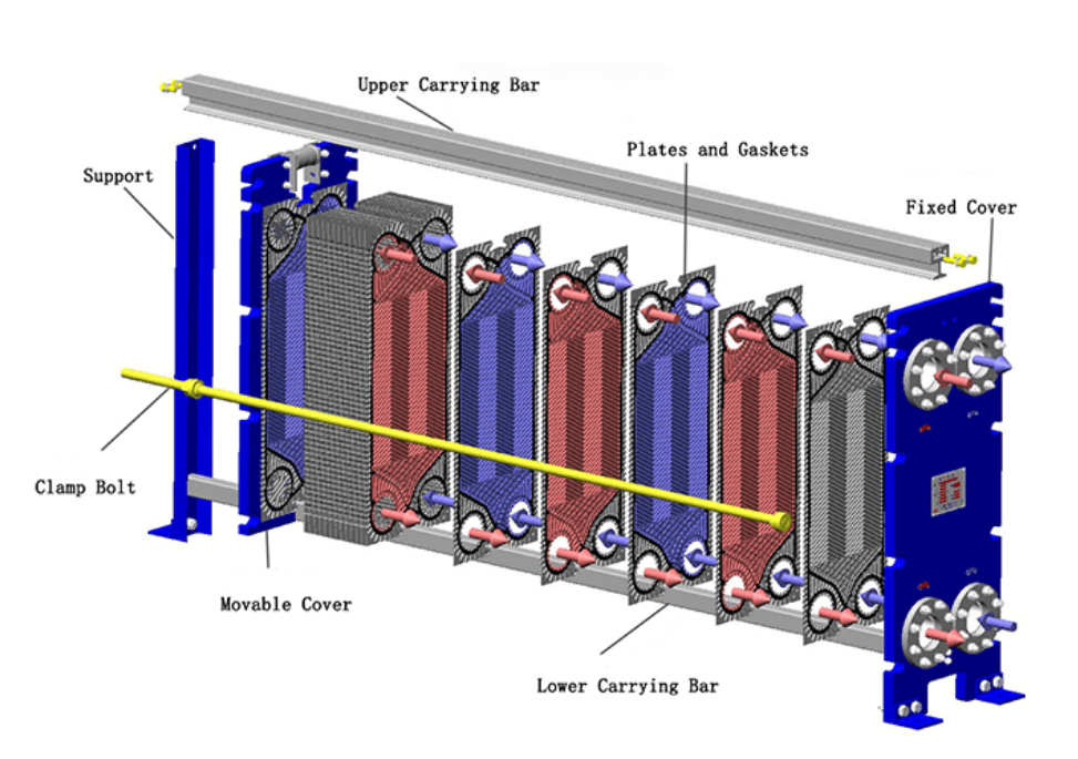
Before exploring the procedures, it is crucial to have a fundamental comprehension of the components that make up the PHE. A typical gasketed PHE contains:
1. Frame Plate: The fixed end of the exchanger, usually containing some of the fluid connection ports. It provides the structural anchor.
2. Pressure Plate: The movable end plate that compresses the plate pack against the frame plate. It may also contain connection ports.
3. Heat Transfer Plates: Thin, corrugated metal plates (often Stainless Steel, Titanium, or other alloys) engineered with specific patterns (like the common chevron pattern) to maximize turbulence and heat transfer surface area. These are the core of the heat exchange process.
4. Gaskets: Elastomeric seals fitted into grooves on the plates. They serve a dual purpose: sealing the channels to prevent external leakage and directing the flow of the two fluids into alternating channels, preventing internal mixing. High-quality gaskets are crucial; browse options at Gasketed Plate Heat Exchanger.
5. Carrying Bar: An upper bar supporting the weight of the plates and the pressure plate, ensuring alignment.
6. Guiding Bar: A lower bar that maintains the vertical alignment of the plates and pressure plate.
7. Tightening Bolts: Long bolts used to compress the entire plate pack between the frame plate and pressure plate to a specific dimension, ensuring a proper seal.
8. Support Column: Provides structural support for the carrying and guiding bars, especially on larger units.
Step-by-Step Assembling
Assembling a gasketed phe, whether new or after maintenance, requires attention to detail. Rushing this stage is a frequent cause of future problems.
1. Preparation is Paramount:
Cleanliness: Ensure all components, especially heat exchanger plates and gaskets grooves, are impeccably clean and free from debris, oil, or old adhesive residue. The assembly area should also be clean.
Inspection: Carefully inspect each plate for dents, warping, or damage to the gasket groove. Examine gaskets for cracks, hardening, swelling, or loss of elasticity. Damaged components must be replaced.
Tools: Gather necessary tools: torque wrench, appropriate spanners/sockets, measuring tape, soft mallet (optional), gasket adhesive (if applicable), lubricant for bolts, and personal protective equipment (PPE) like gloves and safety glasses. Plate edges can be sharp.
Documentation: Have the manufacturer's assembly drawing and specifications readily available. This includes the crucial target tightening dimension.
2. Frame and Initial Setup:
Safety First: Before beginning assembly, ensure you are wearing appropriate PPE, including sturdy gloves (plate edges can be sharp) and safety glasses. Be mindful of component weights during handling.
Position the frame plate securely:Ensure the carrying and guiding bars are correctly attached and aligned.
3. Plate Pack Arrangement:
Orientation: This is the most critical step. Corrugated plates are typically designed to be hung alternatingly (rotated 180 degrees relative to the previous plate). This creates the flow channels. Pay close attention to the plate pattern (e.g., high-theta vs. low-theta plates if mixing) and ensure the correct sequence as per the assembly drawing. An incorrect arrangement leads to bypassing, reduced performance, or internal leaks.
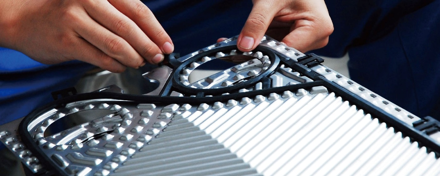
Gasket Alignment: Ensure each gasket is correctly seated in its groove. For clip-on or snap-on gaskets, verify all attachment points are engaged. For glued gaskets, ensure proper adhesion without excess glue squeezing onto the heat transfer surface or obstructing the flow path.
Loading Plates: Carefully hang the plates onto the carrying bar one by one, ensuring they slide smoothly and align correctly at the bottom via the guiding bar. The first plate (start plate) goes against the frame plate, followed by the flow plates in alternating sequence, ending with the last plate (end plate) before the pressure plate. Visually inspect the edge of the plate pack as you build it; a correct assembly often exhibits a characteristic "honeycomb" pattern due to the alternating corrugations.
4. Gasket Installation Differences:
Clip-On/Snap-On: These are generally easier to install. Align the gasket in plate heat exchanger correctly and press it firmly into the groove, ensuring all clips or tabs engage securely.
Glued Gaskets: Apply a thin, even bead of the manufacturer-recommended adhesive into the clean gasket groove. Avoid excessive glue. Carefully place the gasket, ensuring it sits flat without stretching. Allow adequate curing time as specified by the adhesive manufacturer, potentially under light compression (e.g., stacking plates with a board and weight on top).
5. Compression and Tightening:
Position Pressure Plate: Slide the pressure plate along the bars until it contacts the plate pack.
Install Tightening Bolts: Insert the lubricated tightening bolts. Start threading the nuts by hand.
Systematic Tightening: This must be done evenly to avoid damaging plates or skewing the pressure plate. Tighten the bolts incrementally in a diagonal or "star" pattern (e.g., top-left, bottom-right, top-right, bottom-left). Use a torque wrench or tighten by measuring the distance between the inside surfaces of the frame plate and pressure plate.
Measure the Gap: Continue tightening the bolts evenly in a diagonal (star) pattern until the gap between the fixed frame plate and the movable pressure plate matches the manufacturer's specified value (e.g., X mm ± Y mm). Measure this gap at multiple points around the frame, especially near each bolt, to ensure the plates remain parallel and uniformly compressed. Use a calibrated measuring tool, such as a feeler gauge or ruler, for accuracy. Crucially, do not overtighten. Exceeding the maximum compression can deform plates, crush gaskets, and paradoxically cause leaks. Conversely, under-tightening will result in immediate leaks.
6. Final Assembly Checks:
Verify the gap between the fixed frame plate and the movable pressure plate is correct and uniform.
Visually inspect the plate pack edges again for correct alignment.
Check that all bolts are properly secured.
How To Install a Plate Heat Exchanger
Once assembled, the PHE needs correct installation within the broader system.
1. Site Preparation:
Foundation: Ensure a solid, level foundation capable of supporting the filled weight of the exchanger.
Clearance: Provide adequate space around the unit for operation, inspection, and future maintenance (like plate removal or cleaning). A general rule is to allow free space equivalent to the unit's length for bolt removal and plate pack access.
Environment: Protect the unit from physical damage, excessive vibration, and corrosive atmospheres if possible. Consider a drip tray underneath, especially for critical applications or where leakage could damage surrounding equipment.
2. Lifting and Positioning:
·Use appropriate lifting equipment (straps, hoists) and follow manufacturer guidelines for lifting points (often designated on the frame or using specific bolts). Never lift by the connections.
·Carefully lower the unit onto its foundation, ensuring it remains level. Secure it if required by design.
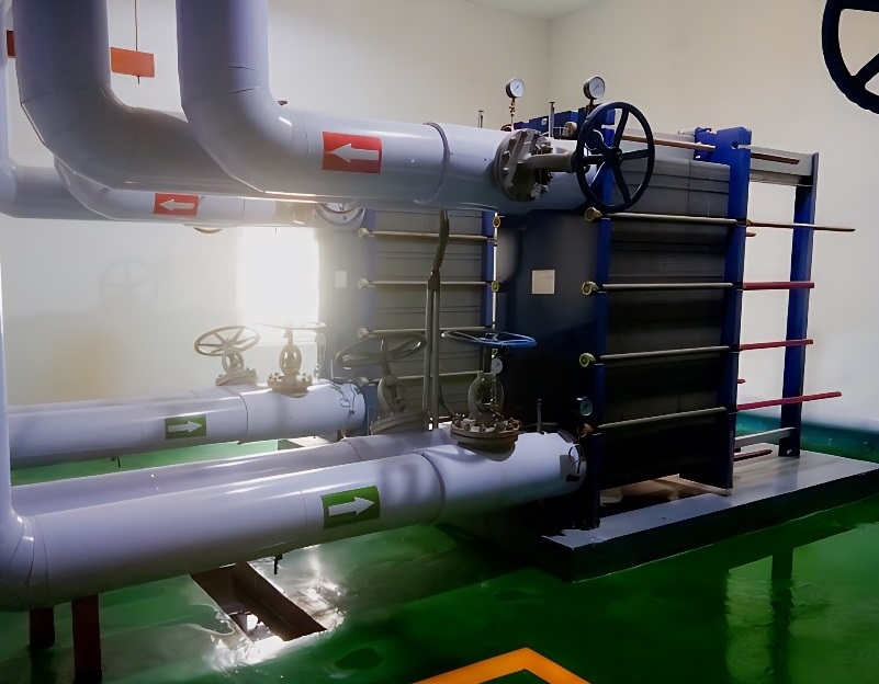
3. Piping Connections:
·Alignment: Ensure connecting pipework aligns perfectly with the PHE nozzles. Avoid forcing pipes into alignment, as this imposes stress on the exchanger frame and connections, leading to potential leaks or damage. Use expansion joints or flexible connectors where necessary to accommodate thermal expansion and vibration.
·Connection Types:
··Flanged: Use appropriate gasket (often supplied by the PHE liner itself if rubber-lined, otherwise use separate flange gaskets compatible with the fluid). Tighten flange bolts evenly in a crisscross pattern. Do not overtighten, especially on tapped frame plate connections.
··Threaded: Use appropriate sealant or tape. Employ two wrenches—one to hold the PHE connection firm and one to tighten the mating fitting—to prevent transmitting torque to the PHE connection itself, which could damage internal seals.
·Flow Direction: Connect piping according to the specified flow configuration (e.g., counter-current flow is most common for optimal efficiency). Inlet and outlet ports are usually clearly marked.
·Support: Independently support all connecting pipework to prevent its weight from bearing on the heat exchanger.
4. Ancillary Equipment:
·Install isolation valves on all inlet and outlet ports for maintenance.
·Consider installing strainers upstream of the PHE inlets to protect the narrow plate channels from particulate fouling.
·Pressure gauges and temperature sensors at inlets and outlets are essential for monitoring performance.
·Install air vents at high points to facilitate purging air during startup.
·Ensure safety relief valves are correctly installed if system pressures can exceed the PHE's design limits.
5. Leak Testing (Hydrostatic Test):
Before introducing process fluids, perform a hydrostatic test. Slowly fill one side of the exchanger with water, venting air. Gradually increase pressure to the specified test pressure (typically 1.3 to 1.5 times the maximum operating pressure, but always consult manufacturer specs). Hold the pressure for a designated period (e.g., 30 minutes) and inspect thoroughly for any external leaks from gaskets, connections, or the frame. Depressurize, drain, and repeat the process for the other side. Address any leaks found (often requiring slight, even tightening within the tolerance, or potentially re-gasketing/reassembly if issues persist).
6. Insulation (If Required):
If the application involves significant temperature differences and energy conservation or personnel protection is needed, insulate the PHE frame and potentially the connections. Ensure insulation doesn't cover weep holes or impede access for inspection.
Troubleshooting while install your Plate Type Heat Exchanger
·External Leaks: Often due to damaged/misaligned gaskets, or uneven tightening. Re-check parallelism; tighten slightly if within tolerance. If persistent, disassembly and inspection are needed.
·Internal Leaks (Cross-Contamination): Usually caused by a perforated plate (corrosion, erosion, pressure shock) or a severely failed gasket. Requires disassembly, plate inspection (dye penetrant testing if needed), and replacement of damaged components.
·Reduced Thermal Performance/High Pressure Drop: Frequently caused by fouling (scaling, sediment, biological growth), incorrect plate assembly (bypassing), or operating conditions deviating significantly from design (e.g., low flow rates causing maldistribution). Cleaning (CIP or manual) is often required. Verify assembly and operating parameters.
·Gasket Failure: Can result from chemical incompatibility, excessive temperature, over-compression, or simple aging. Ensure correct gasket material selection and adhere to tightening specifications. Regular inspection during maintenance is key.
Detail is the key to Durability
The assembly and installation of a plate heat exchanger are not merely mechanical tasks; they are crucial engineering procedures that directly impact system efficiency, reliability, and safety. By adhering to these detailed steps and understanding the potential pitfalls, you can ensure your plate heat exchanger delivers the high performance and long service life it was designed for.
Shanghai Heat Transfer Equipment Co., Ltd. specializes in the design, manufacturing, installation, and service of plate heat exchangers and complete heat transfer systems.
If you need further consultation and discussion, please feel free to contact us.
Email: info@shphe.com
WhatsApp / Cell: +86 15201818405